Optimizing a VxWorks CAN Driver: SJA1000T, PCI, and Loongson 3A3000
📘 Abstract #
Controller Area Network (CAN) is widely used in embedded control systems because of its message-based communication model, reliable error detection, and suitability for distributed real-time applications. However, systems requiring dozens of CAN channels introduce additional challenges involving interrupt load, device discovery, channel management, and fault isolation.
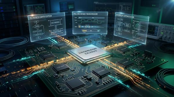
This article presents the design and optimization of an eight-channel PCI CAN communication board based on the SJA1000T controller, targeting a Loongson 3A3000 motherboard running the VxWorks real-time operating system.
The implementation focuses on three areas: replacing transmit-interrupt-driven processing with polling, improving receive-interrupt utilization by scanning all eight CAN controllers associated with a shared interrupt line, and using PCI bus/device/function information to assign stable channel ranges to individual boards.
Experimental results from a three-board configuration demonstrate substantial reductions in interrupt frequency while maintaining useful transmission throughput. The revised device-identification strategy also prevents the removal of one board from changing the channel assignments of the remaining boards.
These techniques illustrate how hardware-aware driver design can improve real-time efficiency, operational stability, and fault isolation in multi-channel embedded communication systems.
🎯 Introduction #
CAN is a multi-master, half-duplex serial communication bus designed for distributed systems in which multiple controllers exchange messages over a shared medium. Its arbitration mechanism, frame-level error detection, and differential signaling make it suitable for automotive electronics, industrial control, instrumentation, and other embedded applications.
VxWorks provides real-time scheduling, interrupt handling, synchronization primitives, and device-driver interfaces that support CAN-based control systems. Depending on the platform and VxWorks release, CAN hardware can be integrated through a BSP-specific driver, the classic I/O system, or an applicable VxBus-based implementation.
However, existing CAN driver implementations may not meet the requirements of systems that combine domestically controlled processor platforms with a large number of communication channels. Drivers originally designed for one or two controllers may experience excessive interrupt overhead when scaled to multiple boards, particularly if transmission and reception generate interrupts for every frame.
This implementation targets the Loongson 3A3000 processor platform and addresses three specific problems:
- High interrupt frequency during CAN transmission.
- Inefficient handling of a shared interrupt line across multiple controllers.
- Unstable channel numbering when a CAN board is missing or removed.
The objective is not simply to increase the nominal CAN bit rate. It is to improve effective communication throughput while controlling CPU overhead and ensuring that hardware failures remain isolated.
🖥️ CAN Communication Board Hardware Architecture #
The CAN communication board provides eight independent CAN interfaces through a PCI-connected design. Its hardware consists of six principal subsystems:
- CPCI bus interface.
- PCI bridge.
- FPGA-based programmable logic.
- Electrical-level conversion circuitry.
- CAN controllers and physical-layer transceivers.
- Power supply and associated circuitry.
The PCI and FPGA logic connect the host processor to the CAN controllers, while the physical-layer components provide the electrical interfaces required by the CAN bus.
SJA1000T CAN Controller #
The design uses the Philips/NXP SJA1000T CAN controller, which supports BasicCAN and PeliCAN operating modes.
PeliCAN mode supports the CAN 2.0B protocol, including extended 29-bit identifiers. The implementation uses PeliCAN mode to provide the required message-format and acceptance-filtering capabilities.
Each controller exposes registers for configuration, transmission, reception, status monitoring, and interrupt control.
Before enabling normal operation, the driver must initialize the controller’s operating mode, clock configuration, acceptance filters, and bus timing. These parameters must correspond to the board’s clock circuitry and the requirements of the connected CAN network.
The controller’s data sheet should be treated as the authoritative reference for register layouts, bit definitions, timing constraints, and interrupt-acknowledgement behavior.
For a complementary hardware and driver overview, see PCI-Based CAN Card Design and VxWorks Driver Development. That guide examines PCI integration, SJA1000-based hardware, device initialization, and interrupt-driven data processing.
🧩 VxWorks Driver Interface Architecture #
In the classic VxWorks I/O system, applications access devices through file-like interfaces. Application requests are dispatched to driver functions registered with the operating system.
The architecture uses three principal structures:
- File descriptor table: Associates an open descriptor with the relevant device and file-operation context.
- Device list: Maintains registered device instances and their names.
- Driver list: Stores registered driver operation entry points.
This model allows an application to interact with a CAN device without directly managing its controller registers.
Driver Registration #
The classic iosDrvInstall() interface registers a set of driver operations:
int iosDrvInstall(
    FUNCPTR create,
    FUNCPTR remove,
    FUNCPTR open,
    FUNCPTR close,
    FUNCPTR read,
    FUNCPTR write,
    FUNCPTR ioctl
);
The registered functions implement device lifecycle operations, opening and closing, frame transmission and reception, and device-specific configuration.
Not every driver needs custom implementations for all seven operations. Functions that are not needed can use appropriate supported defaults according to the target VxWorks release.
After registration, iosDevAdd() associates a device descriptor with its device name and driver number:
int iosDevAdd(
    DEV_HDR *p_hdr,
    const char *dev_name,
    int drv_num
);
Applications can then open the registered device through the supported device interface.
Driver Compatibility Considerations #
The iosDrvInstall() and iosDevAdd() interfaces belong to the classic VxWorks I/O system model. They should not be confused with VxBus driver registration, which uses a different device-discovery, initialization, and resource-management architecture.
For an implementation based on VxBus, consult the SJA1000T CAN controller driver guide for VxWorks. It describes a VxBus-oriented driver structure and the integration of controller resources into a VxWorks image.
The design presented here focuses on the classic I/O interface described in the source implementation. Porting it to another VxWorks version or BSP requires verifying the supported APIs, interrupt model, PCI interface, and controller integration.
⚙️ CAN Driver Design and Core Data Structures #
The driver consists of five primary functional areas:
- I/O interface functions.
- Interrupt handling.
- Driver initialization.
- Device creation and registration.
- Controller-specific configuration and data processing.
The following device structure describes the essential state maintained for an individual CAN channel.
typedef struct
{
    DEV_HDR       can_hdr;       /* VxWorks device header */
    BOOL          opened;        /* Open-state flag */
    MSG_Q_ID      msg_id;        /* Receive message queue */
    unsigned char index;         /* Logical channel number */
    unsigned char mode;          /* Acceptance-filter mode */
    unsigned long baudrate;      /* CAN bit rate */
    unsigned long acc_code;      /* Acceptance code */
    unsigned long acc_mask;      /* Acceptance mask */
} CAN_DEV;
The structure combines operating-system device information with CAN-specific configuration.
The DEV_HDR member allows integration with the classic I/O system. The message queue provides a path from interrupt-driven reception to application-level reads, while the channel number identifies the logical CAN interface.
The baud-rate and acceptance-filter fields store the active configuration for the controller.
A complete implementation should also define initialization state, controller register mappings, transmit timeouts, error statistics, and synchronization mechanisms where needed. Shared state accessed from both interrupt and task contexts must be protected using mechanisms appropriate to the platform.
I/O Interface Functions #
The implementation exposes five principal operations.
| Function | Responsibility |
|---|---|
can_open() |
Configures the controller for operation and returns the relevant device context |
can_close() |
Places the controller into reset mode or an appropriate inactive state and clears runtime status |
can_read() |
Retrieves received frames from the message queue, blocking when the queue is empty if configured to do so |
can_write() |
Transmits frames using polling of the controller’s transmit-buffer status |
can_ioctl() |
Configures the bit rate, filter mode, acceptance code, and acceptance mask |
This API separates CAN communication from controller-specific register operations. Application software submits frames and configures device parameters through the driver rather than directly manipulating the hardware.
🚀 Transmit Optimization: Replace Transmit Interrupts with Polling #
The first optimization targets transmit-side interrupt overhead.
In a conventional interrupt-driven implementation, the driver may generate an interrupt when a transmission completes or the transmit buffer becomes available. Under sustained multi-channel traffic, this can create a large number of interrupts and increase CPU overhead.
The optimized implementation disables the SJA1000T transmit interrupt and polls the controller’s transmit-buffer status instead.
Polling-Based Transmission #
The transmission sequence is:
- Validate the requested CAN frame and its format.
- Check whether the controller’s transmit buffer is available.
- Wait until the buffer becomes available or a timeout occurs.
- Write the frame identifier, control information, and payload into the controller’s transmit registers.
- Trigger transmission according to the SJA1000T programming sequence.
- Record the transmission result and update any relevant status.
A simplified conceptual example is shown below:
/*
 * Illustrative pseudocode.
 * Register names and access functions must match the
 * actual SJA1000T driver and hardware mapping.
 */
STATUS canControllerTransmit(
    CAN_DEVICE *dev,
    const CAN_FRAME *frame,
    unsigned int timeoutTicks
)
{
    unsigned int elapsedTicks = 0;

    if (dev == NULL || frame == NULL)
    {
        return ERROR;
    }

    while (!canTxBufferReady(dev))
    {
        if (elapsedTicks >= timeoutTicks)
        {
            return ERROR;
        }

        taskDelay(1);
        elapsedTicks++;
    }

    if (canWriteFrameRegisters(dev, frame) != OK)
    {
        return ERROR;
    }

    if (canStartTransmission(dev) != OK)
    {
        return ERROR;
    }

    return OK;
}
This example illustrates the control flow rather than reproducing the original register-level implementation. The actual driver must use the correct status bits, register sequence, timing units, and hardware-access routines.
Benefits of Transmit Polling #
Disabling transmit-completion interrupts reduces the number of interrupts generated by normal transmission activity. This is particularly useful when many CAN channels are transmitting continuously.
Potential benefits include:
- Lower interrupt-processing overhead.
- Fewer context transitions associated with transmit events.
- Reduced competition for CPU time between CAN handling and other real-time tasks.
- Simpler accounting of transmit-buffer availability.
Polling is not automatically more efficient under every workload. A poorly designed polling loop can consume CPU cycles while waiting for a buffer, and excessive delays can reduce throughput.
The implementation should therefore use a bounded timeout and a waiting strategy appropriate to the required response time. A busy-wait loop may be appropriate for very short, tightly bounded delays, while a task-level wait or short delay can be preferable when the processor must execute other work.
The critical optimization is to eliminate unnecessary transmit interrupts without introducing unbounded waits or excessive polling overhead.
⚡ Receive Optimization: Traverse All Eight Controllers per Interrupt #
The second optimization addresses interrupt handling across the eight CAN controllers on each board.
The controllers share a single low-level interrupt line. Rather than enabling every possible interrupt source on every controller, the driver enables the receive and error-alarm interrupts required by the implementation.
When the shared line signals an event, the ISR checks the status registers of all eight controllers and processes the controllers that have pending receive data or relevant error conditions.
Shared-Interrupt Processing #
The receive path follows this general sequence:
- Receive an interrupt on the board’s shared interrupt line.
- Inspect the status of the first CAN controller.
- Determine whether the controller has received data or reported an enabled error condition.
- Retrieve pending receive frames and acknowledge the corresponding event.
- Repeat the process for the remaining controllers.
- Return after all relevant sources have been handled.
A simplified representation is:
/*
 * Illustrative pseudocode for a shared interrupt line.
 * Actual ISR signatures and status-clearing rules are
 * hardware- and BSP-specific.
 */
void canBoardInterruptHandler(CAN_BOARD *board)
{
    unsigned int channel;

    if (board == NULL)
    {
        return;
    }

    for (channel = 0; channel < 8; channel++)
    {
        CAN_DEVICE *dev = board->channels[channel];
        unsigned int status;

        if (dev == NULL)
        {
            continue;
        }

        status = canReadInterruptStatus(dev);

        if (status == 0)
        {
            continue;
        }

        if (status & CAN_RX_PENDING)
        {
            canDrainReceiveBuffer(dev);
        }

        if (status & CAN_ERROR_PENDING)
        {
            canRecordControllerError(dev, status);
        }

        canAcknowledgeInterrupt(dev, status);
    }
}
The symbolic functions and status flags in this example must be replaced by the actual controller and driver interfaces.
The implementation must also follow the SJA1000T’s documented interrupt and buffer-clearing behavior. Some status conditions require specific read sequences or acknowledgement operations. Acknowledging an event incorrectly can cause repeated interrupts or lost receive data.
Why Channel Traversal Improves Interrupt Utilization #
The shared interrupt line already indicates that at least one controller requires attention. Inspecting the status of all eight controllers allows the handler to identify multiple pending events during a single interrupt invocation.
This amortizes the interrupt-entry and exit overhead across the controllers and avoids the need to generate a separate transmit-completion interrupt for every frame.
The optimization is particularly useful in a multi-channel system where several controllers can receive traffic concurrently.
However, the ISR must remain bounded. If one or more controllers continuously receive frames at a high rate, draining unlimited data in interrupt context could delay other real-time activities. Implementations should follow a defined processing budget and defer additional work to task context when appropriate.
🧭 Driver Initialization and PCI-Based Board Identification #
Reliable multi-board operation requires stable device discovery and channel assignment.
The system can contain up to three eight-channel CAN boards. Each board needs a unique logical range so that applications can identify channels consistently, even when a board is unavailable.
Discover CAN Boards #
During driver initialization, the implementation uses pciFindDevice() to locate the PCI devices that identify the CAN communication boards.
The returned PCI bus, device, and function numbers are matched against a predefined table.
| Board index | PCI bus | Device | Function | Logical CAN channels |
|---|---|---|---|---|
| Board 0 | 11 | 13 | 0 | 0–7 |
| Board 1 | 11 | 14 | 0 | 8–15 |
| Board 2 | 11 | 15 | 0 | 16–23 |
The identifiers in this table are specific to the target platform and hardware configuration. Different boards or systems may enumerate their PCI devices differently, so the discovery table must be validated against the actual platform.
The driver registers its I/O operations through iosDrvInstall() after establishing the required driver state.
Keep Logical Channel Numbers Stable #
A naive implementation may allocate channel numbers sequentially as boards are discovered. If one board is missing, the remaining boards can shift into different channel ranges.
That behavior creates an application-level hazard: software may continue using a familiar channel number even though it now refers to a different physical CAN interface.
The optimized implementation uses PCI identity to preserve predetermined channel ranges. Board 0 always owns channels 0–7, Board 1 owns channels 8–15, and Board 2 owns channels 16–23.
When creating a device, the driver verifies that the corresponding board is present before registering its channel. Missing hardware is rejected rather than silently reassigned another board’s channel range.
This separates the identity of a physical device from the order in which devices happen to be discovered during initialization.
Stable mapping is particularly important in control systems where logical channel numbers may be embedded in configuration files, application code, or safety-related control procedures.
🔧 Device Creation and CAN Controller Initialization #
The device-creation function accepts a device name and logical channel number. It verifies the existence of the corresponding board, allocates and initializes the device structure, initializes the SJA1000T controller, and registers the device with the VxWorks I/O system.
Device Creation Workflow #
A typical workflow consists of the following stages:
- Validate the requested channel number.
- Identify the board to which the channel belongs.
- Verify that the required PCI device is present and initialized.
- Allocate and initialize the
CAN_DEVstructure. - Establish the controller register mapping and interrupt association.
- Initialize the controller and configure its operating mode.
- Register the device using
iosDevAdd().
If any mandatory operation fails, the driver should release resources that have already been allocated and return an appropriate error.
The implementation must not register a partially initialized channel as operational. Doing so could expose invalid register mappings or synchronization objects to application code.
Initialize the SJA1000T #
The controller initialization sequence follows its documented register programming requirements.
The principal steps are:
- Enter reset or configuration mode through the Mode Register (MOD).
- Configure the clock divider and enable PeliCAN mode as required by the hardware design.
- Configure the operating mode and acceptance-filter behavior.
- Initialize the acceptance-code and acceptance-mask registers.
- Program the bus timing registers for the selected nominal bit rate.
- Configure the required receive and error interrupt sources.
- Enter normal operating mode after the configuration is complete.
The exact register values depend on the controller clock, timing requirements, supported frame types, and board circuitry.
Acceptance filters should normally be configured to receive only the messages required by the application. An unrestricted acceptance configuration can be convenient during initial testing but may increase receive processing and interrupt pressure under heavy traffic.
Complete Device Registration #
After controller initialization succeeds, the driver adds the device to the operating system’s device list using iosDevAdd().
At this point, application software can access the registered channel through the configured I/O interface.
The driver should also provide a clear policy for repeated initialization, duplicate device names, absent boards, and cleanup after failed initialization. These behaviors are essential when the system includes multiple boards and may be restarted or reconfigured during development.
📊 Testing and Performance Analysis #
The driver was evaluated on a Loongson 3A3000 platform populated with three CAN communication boards, providing a total of 24 channels.
Testing focused on transmission efficiency and interrupt frequency at different CAN bit rates. The results compare the original design with the optimized implementation.
Transmission and Interrupt Results #
| CAN bit rate (kbit/s) | Frames/s/channel | Interrupt rate before (events/s) | Interrupt rate after (events/s) | Interrupt reduction |
|---|---|---|---|---|
| 50 | 200 | 3,200 | 1,600 | 50.0% |
| 125 | 500 | 7,996 | 2,038 | 74.5% |
| 250 | 800 | 12,800 | 3,194 | 75.0% |
| 500 | 1,000 | 15,083 | 3,995 | 73.5% |
| 1,000 | 2,000 | 20,618 | 4,182 | 79.7% |
The reduction percentages are calculated from the supplied before-and-after interrupt measurements.
At the lowest tested bit rate, the interrupt rate fell by half. At the higher rates, the reduction ranged from approximately 73.5% to 79.7%.
The results indicate that the combined transmit-polling and receive-interrupt changes substantially reduced interrupt activity across the tested configurations.
The reported frame rates remained high after optimization, suggesting that interrupt overhead was not the only factor determining effective throughput. Controller buffer handling, polling behavior, application processing, and the characteristics of the CAN traffic also affect achievable performance.
The interrupt-frequency measurements alone do not establish worst-case latency, CPU utilization, or behavior under every traffic pattern. Those characteristics should be measured separately when evaluating the design for a strict real-time application.
Fault Isolation and Channel Stability #
The second experiment evaluated the removal of one or more CAN boards.
In the original implementation, channel numbering depended on the set or order of detected boards. When Board 1 was removed, Board 2 could be assigned channels 8–15 instead of its original range of 16–23.
This behavior could cause an application to communicate with the wrong physical channel if it continued using the original logical identifiers.
After optimization, channel allocation remains tied to the predefined PCI identity table.
| Board | PCI bus/device/function | Normal channel assignment | Assignment when Board 1 is absent |
|---|---|---|---|
| Board 0 | 11/13/0 | 0–7 | 0–7 |
| Board 1 | 11/14/0 | 8–15 | Unavailable |
| Board 2 | 11/15/0 | 16–23 | 16–23 |
Board 2 retains channels 16–23 even when Board 1 is absent. The missing board is marked unavailable rather than causing other channels to be renumbered.
This behavior improves predictability and prevents a missing device from silently changing the meaning of existing channel identifiers.
The results demonstrate the importance of separating physical device identity from initialization order. In multi-board systems, stable identifiers are part of the driver’s correctness contract, not merely an implementation detail.
🛡️ Engineering Considerations and Further Optimization #
The reported results provide a useful starting point, but several considerations are important when adapting the design to another board or production workload.
Bound Polling and Preserve Task Responsiveness #
Polling eliminates transmit-completion interrupts but consumes execution time while waiting for the controller.
A production implementation should use bounded waits, appropriate task priorities, and clear timeout handling. The polling interval should be short enough to meet transmission requirements without monopolizing the CPU.
Where workloads are highly variable, a hybrid approach may be worth evaluating. For example, short bounded polling can be used for low-latency transmission, while less time-critical operations can use a task-level wait or an interrupt-driven notification.
Keep Interrupt Processing Bounded #
Traversing eight controller status registers improves the use of a shared interrupt, but the time required for each invocation grows with the number of channels and the volume of pending work.
The driver should avoid performing unrelated application processing or lengthy diagnostic output in the ISR.
If receive queues are saturated, the implementation should provide an explicit overrun policy and, where necessary, defer additional processing to a task. This helps maintain system responsiveness under sustained high traffic.
Handle Shared Resources Safely #
The CAN ISR, device operations, and application tasks may interact with the same message queues, status fields, and transmit buffers.
The driver must apply synchronization appropriate to each execution context. An ISR should not block on a semaphore or acquire a primitive that may sleep.
Status registers also require controller-specific acknowledgement handling. Incorrectly clearing an interrupt or reading status in the wrong order can result in repeated interrupts or lost events.
Improve PCI Discovery Robustness #
The predefined PCI table provides stable mapping on the tested platform, but bus/device/function assignments should be verified for each supported board configuration.
Where multiple identical boards are installed, discovery should use sufficient hardware identity information to distinguish them reliably. The implementation should not assume that PCI enumeration order remains constant across firmware settings or platform revisions.
If a system permits hot-plug or runtime replacement, channel availability and lifecycle handling must be defined explicitly. The original design primarily demonstrates stable behavior when boards are absent; it does not, by itself, establish safe runtime hot-plug support.
Expand Performance Validation #
Additional tests should measure:
- CPU utilization before and after the optimization.
- Mean, high-percentile, and worst-observed transmit latency.
- Receive latency and queue-overrun frequency.
- Behavior under simultaneous activity on all 24 channels.
- Recovery time following controller errors and bus-off conditions.
- System responsiveness while other real-time tasks execute.
- Long-duration stability under representative traffic.
For broader context on PCI-based CAN hardware integration, the PCI CAN card design and VxWorks driver development guide discusses device initialization, register mapping, interrupt handling, and validation.
✅ Conclusion #
This design presents a multi-channel CAN driver for the Loongson 3A3000 platform running VxWorks, using eight SJA1000T controllers per PCI communication board.
The primary optimizations address three distinct sources of inefficiency and instability:
- Polling-based transmission eliminates routine transmit-completion interrupts and reduces interrupt overhead.
- Shared-interrupt traversal processes pending events across all eight controllers, improving the utilization of a common interrupt line.
- PCI-based board identification preserves stable channel ranges and prevents missing hardware from silently renumbering the remaining channels.
Testing on a three-board, 24-channel configuration showed substantial reductions in interrupt frequency while maintaining useful transmission performance. The fault-isolation test also demonstrated that the remaining boards retained their assigned channel ranges when Board 1 was absent.
These techniques are relevant to embedded systems that combine multiple CAN controllers, shared interrupts, and strict real-time requirements. Their effectiveness depends on the controller’s behavior, the platform’s interrupt architecture, and the workload being executed.
For reliable deployment, polling must remain bounded, interrupt handlers must have predictable execution time, shared data structures must be synchronized correctly, and PCI device discovery must be validated against the actual hardware configuration.
By combining these measures with systematic performance testing, developers can improve the efficiency, reliability, and maintainability of multi-channel CAN communication systems under VxWorks.